7/11/14
pjk
Specifying Precision Rollers
Abstract:
Tolerance requirements for rollers continue to become more stringent as quality demands for films and coatings increase. This is further driven by competitive pressures to save money on raw materials. Ideally, the rollers in the work station would be perfect cylinders,which would provide perfectly uniform films or coatings. Whether it is a hard roll or a rubber roll, the reality is that they are not and tolerances must be specified. The tolerances specified should be adequate for the application and maybe even a little tighter to account for wear over time. Under specifying will result in poor performance,but over specifying can be costly. Geometric tolerances can be misinterpreted, therefore it is best to work with your roller company so that there is a mutual understanding of the tolerances, intent and capabilities of inspection. This paper takes a look at specifying roller tolerances and how to be sure you are receiving what you are asking for.
Discussion:
Traditionally,roll covering tolerances consist of diameter for size, runout,taper for diameter variation, surface finish and crown amount if this is involved. Runout and taper are often the primary tolerances to control. It varies by industry and roll position,however as a general rule standard rubber roll tolerances for runout and taper are .003″, .005″ respectively. Much tighter tolerances are certainly achievable and can be as low as .0002″ and .0005″ for runout and taper. As tolerances get tighter, much more collaboration with the roll company is advisable.
Runout and taper are most commonly used because they can be verified with traditional instruments such as dial indicators and PI tapes. Runout requires a datum reference, which is typically and ideally the bearing surface, but in reality it is often the centers. When a standard roll is ground, it is generally held in the grinder by centers and the operator adjusts the head and tail centers to achieve the bearing surface runout to specifications. Many roller companies will assume, without actually checking,that the rubber portion of the roll to now be in within the specified runout value since the roll is ground in the set up. This assumption is made because contact dial indicators are difficult to maintain accuracy on compliant rubber surfaces. More modern techniques use non-contact devices such as proximity sensors, lasers or LED micrometers. With these devices,the actual rubber roll surface can be measured, but since circular runout is a station by station measurement, the number of measurements across the roll must be specified,including the bearing surfaces.
Total indicated runout or (TIR) is often used and maybe confused with circular runout. TIR is much more stringent than circular runout because it controls all elements of a surface simultaneously including diameter. For example, if 0.0005″ TIR was specified and all of the surfaces had zero runout,the roller would fail if the radius changed by more than 0.0005″. This can lead to over specification if the diameter requirement is not needed. In practice,when TIR is called out,multiple individual runout readings are taken and diameter change is often ignored but considered in the taper requirement. Similar to runout, it is important to know how many stations are being measured and included in the TIR calculation.
As tolerances become tighter, further consideration must be taken into account regarding the roll fixturing during the grind and inspection process. Supporting the bearing surfaces during the grinding process takes out any runout error between the centers and bearing surface. Once the roll is assembled however, bearing runout will be added to the assembly. Taking it a step further,to incorporate bearing runout, the roll could be ground as a complete assembly on bearings. Careful consideration must be given to the selection of the bearings and design of assembly or it could make matters worse. Bar marks or chatter can appear if the bearing system is not set up properly.
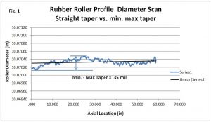
The taper requirement is another important tolerance that must be mutually understood between the customer and roller company. There is no geometric tolerance symbol for taper, but it is used quite universally in the roller industry. Even then,it can be interpreted differently by roller companies. Just as the term suggests,it is a linear change in diameter between two specified points. More measuring points can be added and typically it is three to five points taken across the roll with a Pi tape. A straight line could then be interpolated and the end points of the line taken as taper. Conversely, for other roller companies taper can simply mean the (max- min) of the diameters taken regardless of location. This can be a much more stringent interpretation. The plot in Figure 1, shows a profile with a linear trend line. Even though the profile has hills and valleys, the trend line has very little slope. If taper is taken as the end points,it becomes almost zero, whereas, the max-min measurement is .0004″. Pi tapes and micrometers are traditionally used to measure the diameters. Pi tapes have limited accuracy of about 0.002″ and because there is some operator skill involved,their reproducibility on rubber adds a variable. Micrometers have similar issues on soft elastomeric roll covers.
Cylindricity is occasionally used on roller drawings. Like TIR, cylindricity is an all-encompassing geometric tolerance that addresses the shape of the cylinder in terms of allowable variation from the central axis. Similar to TIR, multiple measurements of diameter and runout are taken and values are determined based on the highs and lows. When using discrete measurement tools, determining cylindricity of a roller can be quite time consuming. One very important consideration when using the geometric with rollers, is that,unlike TIR, cylindricity does not use a datum reference. It strictly addresses the form of a cylinder,and therefore concentricity to a bearing surface is not a requirement.
Concentricity is also only occasionally specified and will usually be interpreted as runout. A runout measurement encompasses both the circularity of the roller as well as eccentricity to the reference surface axis in a simple measurement. Concentricity applies to the eccentricity of the axes and does not necessarily include the form of the circle. Although computerized methods make it much easier, it is still much more difficult to truly determine concentricity. To determine concentricity, a set up similar to runout is commonly used. The data is then analyzed to determine the area center of mass. The difference between the axis centers is concentricity.
As tolerances become tighter,point to point measurements and accuracy limitations of contact measurements become inadequate as significant variations in the profile may be missed. These limitations ca n be overcome with modern non-contact measurement systems. Such instruments can be incorporated into a roll inspection system in a number of different ways, and can have important effects on the final data . The roll could be moved from the grinder to an inspection station,or inspected right at the machine which helps to maintain the references used to grind the roller should the roller need more work. The measuring device could be moved to discrete locations along the roller face to measure both runout and diameter or it can be traversed across the roller to form a continuous profile with the roll stationary or rotating. If the roll is held stationary, additional profile measurements can be taken by profiling numerous clocking positions of the roller. If the roll is scanned while rotating and traversing, both runout and diameter measurements can be recorded to form a composite TIR or cylindricity measurement.
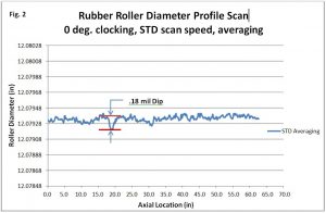
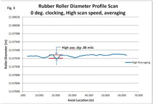
Often times, discreet measurements of both runout and profiles are preferred when the data is later used to study webs or coatings the roll has made. Composite cylindricity information can be confounding when making these correlations. Additional information to understand when non-contact data is gathered, are the capabilities and settings of instrument. Ideally, the accuracy and repeatability should be ten times better than the requirement. It is also important to know the scan rate and averaging setting of the instrument. These devices have a certain scan rate, and will calculate a running average of values, which is the output value. A high averaging count will produce a nice smooth curve, but can easily “average out” undulations in the profile. Likewise, moving the measuring device or part too fast will produce a similar “hiding effect” . Setting the average too low, will produce a jittery or choppy profile that can pick up particles of dust or the instability of the raw reading. This extreme also has limited use because the underlying profile is somewhat masked. Figures 2 and 3 illustrates the setting changes on a light based micrometer. As shown in Fig. 2, this roll has a .18 mil low spot spanning about 3″ in the profile. Fig. 3 shows a scan with a high averaging setting. It produces a nice smooth even profile, however the low spot is mitigated to about .08 mil.
Adding to the complication of specifying a precision roller, may be the need to control the abruptness of the deviation from the cylindrical shape. Take for example,a taper specification of 0.0005″. If the roll is truly a straight taper most processes can be adjusted. The opposing roll, doctor blade or die can be adjusted accommodate the 0 .00025″ radius change. Conversely, if there is a 0.0005″ dip in the profile that is concentrated in a short span,it is much more difficult to adjust a straight opposing surface. The result will be a cross web high or low spot. This is where a modifier or qualifying adder is needed to the specification. Wording can be added to include a reduction in the tolerance if the change takes place in less than a certain span. Or a qualifier can be added to only allow no more than x amount of deviation from a linear regression line through the data. Again, it stresses the need to work with your roller company to convey what you need.
Finally, the inspection of a precision roller should take place after the roll has stabilized in temperature. Grinding processes generate heat, which affects the shape ofthe roller because temperatures are not necessarily uniform. This is especially true with an elastomer cover which is an insulator and has an expansion coefficient lOx that of steel. It can take as much as 8-16 hrs. for a rubber covered roll to stabilize. This can tie up equipment for a long time, and many roller companies are reluctant to do so, however it is essential to allow the roll to stabilize.
Conclusion:
Precision rollers require a properly designed core, bearing set and high quality elastomeric cover (if used). Beyond that, the tolerance and method of finishing needs to be conveyed with the roll vendor. The traditional parameters such as diameter, runout, taper, and surface finish are adequate, but may require additional qualifiers to meet the needs. It is best to work with the roller company to establish a mutual understanding of the requirements and methods of finishing. A visit to the roller company during processing and inspection of your roller is also beneficial.
To view a pdf version, click here.